01
Problem
The car plays audio from my phone through a 3.5 mm bluetooth aux receiver, which leaves every track change on the phone itself. The usual fix is a replacement head unit with CarPlay, which costs hundreds of dollars and removes the 2000s look to the interior of the car.
The steering wheel already has six buttons wired to the head unit. My first plan was to wire each button to its own GPIO (general-purpose input/output) pin on a microcontroller and read them as switches. Opening the wheel wiring revealed that only two conductors run to the button board. The buttons form a resistor ladder, so each one pulls the signal line to a different voltage, and the head unit decodes which button is pressed from that level alone.
That turned a digital-input problem into an analog one. The job became reading a single voltage accurately enough to tell seven states apart, at a level the microcontroller could safely accept, without disturbing the head unit that still depends on the same line.
02
Requirements & constraints
| Parameter | Value | Where it came from |
|---|---|---|
| Ladder signal, no button pressed | 4.4 V | Measured at the button line; the ladder runs from a 5 V reference |
| Lowest ladder level | 0.422 V | Measured, Vol− pressed |
| ESP32 ADC input ceiling | 3.3 V | GPIO pins run on 0-3.3V |
| Media functions needed | 3 | Next track, previous track, play/pause |
| Buttons free to repurpose | 2 | Up and Down, which I never use |
| Buttons left to the head unit | 4 | Mute, Mode, Vol+, Vol− keep their factory behavior |
| Connection to the car | Parallel tap | No cut or spliced factory conductors; fully reversible |
| ADC block | ADC1 | The radio is running the whole time; ADC1 is the block to use alongside it |
Three functions from two buttons is the constraint that shapes the firmware. The 3.3 V ceiling is the one that shapes the hardware.
03
Design
Characterizing the ladder
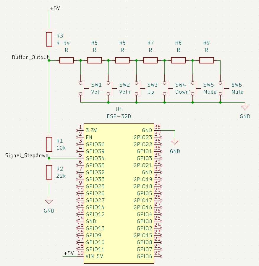
I metered the signal line with each button held and with nothing pressed. Each button closes to a different tap on a series string of resistors, so the level steps down from Mute at the far end of the string to Vol− nearest the pull-up.
| Button | At the ladder | After the divider | Handled by |
|---|---|---|---|
| No press | 4.40 V | 3.03 V | — |
| Mute | 3.83 V | 2.63 V | Head unit |
| Mode | 3.15 V | 2.17 V | Head unit |
| Down | 2.42 V | 1.66 V | ESP32 |
| Up | 1.68 V | 1.16 V | ESP32 |
| Vol+ | 1.00 V | 0.69 V | Head unit |
| Vol− | 0.422 V | 0.29 V | Head unit |
Bringing 4.4 V under 3.3 V
A two-resistor divider scales the line into range. With 10 kΩ on top and 22 kΩ to ground, the highest level the pin ever sees is 3.03 V.
Choosing the input pin
The divider output lands on GPIO34. It is an input-only pin on ADC1 with no internal pull-up or pull-down, so nothing inside the ESP32 can drive or bias the shared line. The choice of ADC block matters as much as the pin: the ESP32 shares ADC2 with its radio driver, and this board has Bluetooth running continuously.
Deciding in ADC counts, not volts
The ESP32 ADC is not especially linear, and its reference varies from chip to chip, so converting readings back to volts would add error without adding anything useful. Instead the firmware stores the raw 12-bit count for each button, measured on this board with the divider in circuit, and places each decision threshold at the midpoint between neighboring buttons. Recalibrating means holding each button, reading the settled count from the serial monitor, and changing seven numbers.
Scale is the full 12-bit range, 0–4095. Only the Down and Up bands produce a command; every other level reads as no press.
The thresholds that matter all sit between 1148 and 2376 counts, roughly 0.9 to 1.9 V at the pin. That is the part of the ESP32’s range, at 11 dB attenuation, where the converter behaves best. Mute and the idle level sit near the top of the range, where the ADC is least linear, but both only ever need to read as “not Down,” so the distortion up there costs nothing.
Two buttons, three functions
Up is the simple case: a completed press sends next track. Down carries two jobs. A single press sends play/pause, and two presses in quick succession send previous track. To tell them apart, the firmware holds a Down release for 300 ms. If a second release arrives inside that window it sends previous track; if the window expires first it sends play/pause. Every command fires on release rather than on press, which is what makes that wait possible.
Two filters sit in front of that logic. A reading only counts once five consecutive samples, taken about 10 ms apart, agree on the same button — each sample itself the average of eight conversions. That rejects contact bounce, and it also rejects the instant a volume press passes through the Up or Down band on its way to a lower level. Second, a press held longer than 500 ms is discarded, so holding a button for its factory function never produces a stray track change. While no phone is connected, the firmware tracks the line without acting on it, so a button held through a reconnect does not fire the moment the link comes up.
Firmware (Arduino, ESP32)
// Mazda 3 steering wheel control adapter.
//
// Taps the factory SWC resistor ladder through a 10k/22k divider into GPIO34
// and translates Up and Down presses into BLE media commands. Mute, Mode,
// Vol+ and Vol- are left alone so the head unit keeps handling them.
#include <BleMediaControl.h>
// This enum must stay above the first function definition in the file. The
// Arduino build injects auto-generated prototypes at the location of the first
// function it finds, and several of those prototypes take a Button.
enum Button { BTN_NONE, BTN_DOWN, BTN_UP };
BleMediaControl media("Car Audio Controller");
const int PIN_SWC = 34;  // input-only, correct for a passive parallel tap

// ---------------------------------------------------------------------------
// CALIBRATION
//
// Raw ADC counts read on GPIO34 with the divider in circuit. Open the serial
// monitor at 115200, hold each button, and record the settled "ADC:" value.
// Boundaries recompute themselves from these seven numbers.
// ---------------------------------------------------------------------------
const int RAW_STANDBY = 3673;
const int RAW_MUTE    = 3264;
const int RAW_MODE    = 2693;
const int RAW_DOWN    = 2060;
const int RAW_UP      = 1440;
const int RAW_VOL_UP  =  856;
const int RAW_VOL_DN  =  360;

constexpr int midpoint(int a, int b) { return (a + b) / 2; }
const int THRESH_DOWN_MAX = midpoint(RAW_MODE, RAW_DOWN);
const int THRESH_DOWN_MIN = midpoint(RAW_DOWN, RAW_UP);
const int THRESH_UP_MIN   = midpoint(RAW_UP, RAW_VOL_UP);

const int SAMPLE_COUNT    = 5;    // consecutive reads that must agree
const int SAMPLE_INTERVAL = 10;   // ms between samples
const unsigned long HOLD_IGNORE_MS = 500;  // ignore a button held longer
const unsigned long DOUBLE_TAP_MS  = 300;  // double-press window on DOWN

Button stableButton    = BTN_NONE;
Button candidateButton = BTN_NONE;
int    candidateCount  = 0;
unsigned long buttonPressTime = 0;
bool          downPendingSingle = false;
unsigned long downReleaseTime   = 0;

int readADC() {
  const int READS = 8;
  long sum = 0;
  for (int i = 0; i < READS; i++) {
    sum += analogRead(PIN_SWC);
    delayMicroseconds(200);
  }
  return (int)(sum / READS);
}

Button classifyADC(int adcVal) {
  if (adcVal >= THRESH_DOWN_MAX) return BTN_NONE;  // standby, Mute or Mode
  if (adcVal >= THRESH_DOWN_MIN) return BTN_DOWN;
  if (adcVal >= THRESH_UP_MIN)   return BTN_UP;
  return BTN_NONE;                                 // Vol+ or Vol-
}

void handleDownTimeout() {
  if (downPendingSingle && (millis() - downReleaseTime) > DOUBLE_TAP_MS) {
    downPendingSingle = false;
    media.send(MEDIA_PLAY_PAUSE);
  }
}

void onButtonReleased(Button btn) {
  if (btn == BTN_UP) {
    media.send(MEDIA_NEXT_TRACK);
    return;
  }
  // BTN_DOWN: single tap = play/pause, double tap = previous track
  unsigned long now = millis();
  if (downPendingSingle && (now - downReleaseTime) <= DOUBLE_TAP_MS) {
    downPendingSingle = false;
    media.send(MEDIA_PREVIOUS_TRACK);
  } else {
    downPendingSingle = true;
    downReleaseTime   = now;
  }
}

void setup() {
  Serial.begin(115200);
  analogReadResolution(12);
  analogSetAttenuation(ADC_11db);
  media.begin();
}

void loop() {
  int adcVal     = readADC();
  Button current = classifyADC(adcVal);

  // Runs whether or not a phone is connected, so calibration works on the
  // bench. Comment out once the RAW_* values are dialed in.
  Serial.print("ADC: ");     Serial.print(adcVal);
  Serial.print("  Button: "); Serial.print((int)current);
  Serial.print("  BLE: ");    Serial.println(media.isConnected() ? 1 : 0);

  if (!media.isConnected()) {
    // Track the reading without firing, so a button held through a reconnect
    // does not register as a press the moment the link comes up.
    stableButton    = current;
    candidateButton = current;
    candidateCount  = 0;
    downPendingSingle = false;
    delay(SAMPLE_INTERVAL);
    return;
  }

  handleDownTimeout();

  if (current == candidateButton) {
    candidateCount++;
  } else {
    candidateButton = current;
    candidateCount  = 1;
  }

  if (candidateCount >= SAMPLE_COUNT && current != stableButton) {
    if (current == BTN_NONE) {
      if (stableButton != BTN_NONE &&
          (millis() - buttonPressTime) < HOLD_IGNORE_MS) {
        onButtonReleased(stableButton);
      }
    } else {
      buttonPressTime = millis();
    }
    stableButton = current;
  }

  delay(SAMPLE_INTERVAL);
}
04
Build
The divider is soldered on perfboard alongside the ESP32 development board. To find the steering wheel pair at the back of the stereo, I used a published harness pinout for the first-generation Mazda 3, which lists the steering wheel control leads on pins 12 (white/black) and 13 (brown/yellow). The divider input connects to the signal conductor and the board ground to the return, both as parallel taps, so the head unit connector stays fully populated and the factory path is unchanged.
The ESP32 is powered through a USB-C cable routed from a cigarette lighter through the dash, which keeps the 12 V system out of the build entirely: the only connection to the car’s wiring is the two-wire tap.
| Connection | From | To |
|---|---|---|
| Steering wheel signal | Head unit harness, SWC pair | Divider input (10 kΩ side) |
| Steering wheel return | Head unit harness, SWC pair | ESP32 GND and divider bottom (22 kΩ side) |
| Scaled signal | Divider midpoint | GPIO34 (ADC1) |
| Power | USB-C cable through the dash | ESP32 board |
05
Verification
Each calibration value is the settled reading on GPIO34 with the button held and the divider in circuit. Margin is the distance from that reading to the nearest threshold — how far a level can drift before the firmware would misread it.
| Button | Predicted at pin | Measured | Reads as | Margin to nearest threshold |
|---|---|---|---|---|
| No press | 3.03 V | 3673 | None | 1297 |
| Mute | 2.63 V | 3264 | None | 888 |
| Mode | 2.17 V | 2693 | None | 317 |
| Down | 1.66 V | 2060 | Down | 310 |
| Up | 1.16 V | 1440 | Up | 292 |
| Vol+ | 0.69 V | 856 | None | 292 |
| Vol− | 0.29 V | 360 | None | 788 |
The tightest margin is 292 counts. That is the Up/Vol+ boundary, about 0.23 V at the pin and 0.34 V back at the ladder. The two levels the firmware acts on each have at least 290 counts of room on both sides — a drift of more than 20 percent of the Up reading before it could be mistaken for a neighbor.
The measured counts fall in the same order as the scaled voltages, with no two levels crowding each other after scaling. Placing each threshold at a midpoint means neighboring buttons share their margin evenly, so no single boundary is the weak one by construction.
06
What I’d do differently
Time the double press from release to next press
The 300 ms window runs from the first release to the second release. A second press that starts inside the window but is held a little too long lets the window expire mid-press: play/pause fires, and the second release then starts a new single press that fires play/pause again. Measuring from the first release to the start of the second press, and suppressing the timeout while Down is held, would make a deliberate double press register as previous track regardless of how long each tap lasts.
Load the ladder less
The 32 kΩ divider draws 0.14 mA from a line the head unit is also reading. That is small, but it shifts every level the head unit sees by an amount that depends on a pull-up I have not measured. A 100 kΩ / 220 kΩ divider keeps the same 0.6875 ratio at a tenth of the load, and a small capacitor at GPIO34 gives the ADC a low-impedance source to sample from.
Protect the input
A car’s wiring is not a bench supply. A series resistor and a clamp diode to 3.3 V ahead of GPIO34 would cost a few cents and keep a transient on the steering wheel line from reaching the ESP32 pin.
Move from perfboard to a board
A small printed circuit board would carry the divider, the protection parts, and a connector that mates with the harness tap, replacing hand wiring that has to survive vibration behind the dash.
Harness pin assignments from a published first-generation Mazda 3 stereo wiring chart. Schematic drawn in KiCad. Ladder voltages measured with a multimeter; ADC counts read from the ESP32 serial monitor with the divider installed.